
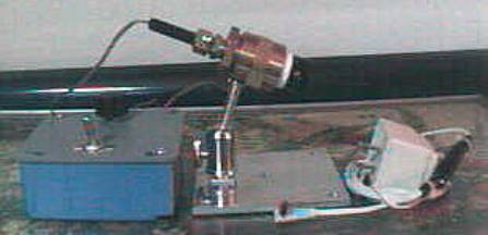
This is my complete LED Illuminator setup,
including AC Mains adapter.
The black bulge in the adapter cord is heat
shrink tubing covering a 7805
voltage regulator IC, and 2 diodes to regulate
the adapter to 6 VDC.
The LED runs at 0.53mA minimum, & can go to
30mA if needed.
Focus,
Mount, and Lighting
|
|
The condenser lens is made from parts of a couple old eyepieces. I
think it’s about 10X. The eye lens is
nearer the LED. The LED is glued into
the end of an old ballpoint pin body. The body is made from plumbing parts. (¾” double female coupler,
¾” to 3/8” reducer, & 3/8” male to compression fitting) I removed the compression ring, reamed the
compression side to fit the LED/pin. Then I drilled & tapped a 6-32 hole
for a setscrew to hold the LED/pin for focussing. The large part of the body is drilled & tapped ¼-20 for the
mount. A few layers of Teflon tape, & the lens can then screw into the ¾”
fitting. The mount is a standard photo ball & socket mount, & the base
is a 4” x 4” x ¼” aluminum plate. I drilled a ¼” hole for the camera mount,
then drilled and tapped 3 holes ¼-20 near each corner & the center so I
can use a table top tripod if I need more height. |
Power
and control
|
|
The box is a plastic 4 x 4 electrical box with
cover. Except for the potentiometer (pot)
and box, everything in the pic came from my junk box. The battery holders are held in place with
Velcro. The circuit is simple. It’s just the LED,
5K pot, 50 ohm resistor, switch, and 6 volt battery (4xAA) in series. I also
added a jack that disconnects the batteries when the AC adapter is plugged
in.
|

My LED illuminator in use |
|
|
|
|
For more info please read the online article “The LED lamp“, on which my LED illuminator is based, part of the “The Quekett Microscopical Club“ site.
Thanks Quekett!