S38 Timing Chain Replacement (without removing the head)
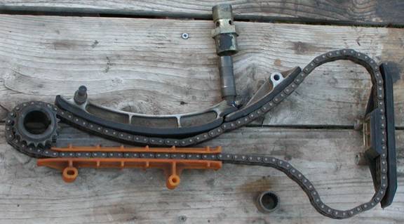
The main parts to
replace
I
recently replaced the timing chain and associated parts on my 1988 M6. I’d heard that this is a good thing to do as
failure of these parts can turn the engine into scrap in a millisecond. Apparently the replacement process was
decided by secret proclamation, as I have never found any details about it
beyond “take it to a good shop and give them boatloads
of money”. This advice is typically
followed by words to the effect of “you’d have to be crazy, stupid, or
desperate to try it yourself”. In
hindsight, I must agree. But would I do
it again? You bet. I don’t have a good shop to go to or
boatloads of money to give away.
I
have no idea what the differences are between the various flavors of the S38
engine. My 1988 M6 is the B35 version. It had 134K
miles on all original parts. I also
decided to replace all the coolant hoses as part of this job since they’d be
accessible. I almost pulled the head too, (even bought the bolts, gasket,
o-rings, etc.). I imagine the secret BMW
proclamation directs this, but I found it wasn’t absolutely necessary.
Parts Used
11
14 1 726 731 – Timing cover gasket left
11
14 1 726 733 – Timing cover gasket right
11
14 1 715 100 – Main seal in timing cover
11
14 1 315 085 – Oil pan gasket
12
11 1 252 257 – 2 ea. O-rings for sealing cam sprocket covers
11
14 1 271 415 – O-ring, rotor shaft
11
23 1 308 128 – Hub nut
11
21 1 252 573 – Lower timing chain sprocket
11
31 1 308 550 – Upper chain guide
11
31 1 403 081 – Timing chain
11
31 1 309 945 – Main chain tensioner rail
11
31 1 317 335 – Upper chain tensioner rail
11
11 1 308 657 – Main tensioner rail pin
07
11 9 906 328 – 2ea. O-ring, main chain tensioner
11
31 1 304 257 – Idler shaft o-ring
11
31 1 307 408 – Upper tensioner shaft o-ring
11
31 1 307 782 – Chain tensioner kit (piston, cylinder, spring)
11
31 1 305 070 – 2ea. Folding washer for cam sprockets
11
51 1 256 654 – water pump gasket
11
31 1 308 495 – Timing chain guide
11
12 1 312 173 – 3ea.
11
12 1 312 172 –
Initial Disassembly
There
is no room to work on this engine. All
the parts around the front of the engine had to come off to provide access to
the timing chain area and room to work.
This is the easy stuff. The only
hard part was keeping track of all the nuts and bolts.
I
started by removing the hood. Those
hoses that feed washer fluid to the frogs, I cut them and used little drip
irrigation couplings to put them back together when I put it back on. Then I
put the front of the car on jack stands so I could get underneath.
1. Removed the
fan. Reverse thread, 1¼” open end
wrench. Had someone squeeze the belts
while I smacked the wrench with a hammer.
2. Removed the
radiator and fan shroud. I couldn’t find
any coolant drain on the M6. Instead, I
yanked hoses and let the stuff run all over and make a big mess.
3. Removed the
fan belts.
4. Removed the
air box, airflow meter, intake assembly (basically everything upstream from the
throttle bodies) Left the throttle bodies in place.
5. Disconnected
the battery and removed the alternator.
6. Unbolted the
power steering pump from the bracket that holds it (and the alternator) to the
block, then removed the bracket. Used a bungee cord to hold the pump up and
out of the way.
7. Removed the
distributor cap and ignition wires.
Covered the open tubes that go to the spark plugs with a sheet of
tinfoil so stuff wouldn’t get in there.
8. Removed the
distributor rotor and the round casting behind it (3 bolts).
9. Removed the
crank sensor and bracket that’s bolted to the timing cover, passenger side.
10. Removed the
pulley on the end of the water pump and then the pump.
11. Removed the
pulley from the end of the crankshaft and the harmonic balancer.
Initial Cleanup
I
could now see the whole timing chain cover and everything from the cam cover to
the oil pan was open and reasonably accessible.
It was also filthy. Started with a little plastic scraper to remove heavy gunk. Followed up with brake
cleaner and a small scrub brush. Still dirty. More
brake cleaner, rags, and an old toothbrush worked for removing every trace of
dirt from the front of the engine.
Oil Pan Removal
The
oil pan had to be removed to make room for taking off the timing chain cover. (The timing chain cover is clamped between
the oil pan and the head.) First I
removed the upper nuts on the engine mounts (17mm socket). Then I used a floor jack placed under the
front of the oil pan with a board on top of it (to prevent damaging the oil
pan) to gently lift up the engine about 2”.
Then I place small wood blocks on top of the engine mounts to hold the
engine up after the floor jack was removed.
Next I drained the oil and began removing all the bolts around the oil
pan. When I got to the rear I found the
back of the oil pan was covered by a big cast plate that is part of the bell
housing. 4 of the bolts holding this
plate on have a weird metric torx head.
I found a socket (E10 is the marking on it) that fit in a set at the
auto parts store for $17. Once this
plate is removed it can be wiggled out of the way to gain access to the back of
the oil pan. Once the oil pan was free
I had to unbolt the oil pump to remove the pan.
Three M8 (13mm head) bolts and 2 M6 bolts (10mm head) hold the pump to
the engine. The pump is chain driven and
the chain sprocket must be removed also.
The M10 (17mm) nut comes off and the spline shaft then slides out of the
sprocket. I dropped the pump into the
oil pan and slid the whole mess down and out the front to remove it.
The Hub Nut
There
is a really big (36mm) collar nut on the end of the crankshaft that has to come
off before the timing chain cover can be removed. It was originally installed at 325 ft./lbs. Because it’s a
collar nut with a big flat flange (more surface area compressed against the
crank hub than a normal nut) and it had been on there for 16 years, it would
take a lot more than 325 ft./lbs. to break it
free. If I ever do this job again, I
will buy a harmonic balancer from a junkyard and have a piece of pipe long
enough to reach under the frame welded to it.
I would bolt this to the crank hub and use it to lock the engine. Then I would buy a six-point 36mm ¾” drive
impact socket and a ¾” drive breaker bar. A set up like this with a 4-5 foot
cheater pipe and 2-3 guys pulling really hard would probably break this nut
free. I say probably because I talked to
one guy who did just this to remove his hub nut years ago and ended up breaking
off the threaded stub on the end of the crankshaft instead.
What
I did was buy a 6-point ½” drive impact socket and a
high quality ½” drive breaker bar and attempted to use this to remove the
nut. I used a 5-foot cheater bar and had
someone put the car in 3rd gear and press hard on the brakes while me and a friend pulled as hard as we could on the cheater
bar. No joy, it wouldn’t budge.
My
friend thought the breaker bar was too short and got his longer one. The longer bar would reach the frame so we
braced it there and then cranked the starter.
Still wouldn’t break free. Next
we tried heating the nut with a torch and tried the starter trick again. No good.
Lastly my friend put the long cheater bar on his long breaker bar and we
pulled as hard as we could with someone on the brakes. SNAP!
The breaker bar broke and the nut hadn’t budged.
I
cut the nut off. This took about 4
hours. I started by making a series of
cuts angled at 45 degrees where the flats on the nut meet the collar. I used 2” re-enforced cutting wheels on a
Dremel tool. I had to be careful not to
angle in too sharply because I didn’t want to cut into the crank, I just wanted
to relieve the compression on the collar of the nut. This was tedious, cut, turn
the engine, cut, repeat. Eventually I reached a point where I felt I couldn’t
safely cut away any more. Tried the
breaker bar and cheater again and it still wouldn’t move. Next I cut down the nut parallel to the
threads. I eyeballed it and got lucky,
what I should have done was laid a hacksaw blade on the exposed threads and
used this as a guide for the cutting wheel to prevent cutting too close to the
threads on the crank. Once this cut
intersected the angled cuts a big chunk of nut fell off and I was able to brush
the cutting wheel across the fresh cut until the edge of the internal threads
just became visible. I turned the engine
over and repeated this on the opposite side of the nut. This time I nicked 3 threads on the crank but
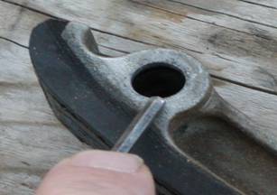
it worked, using the breaker bar the nut came free. Once it was free it spun off by hand. Here’s a picture of the nut:
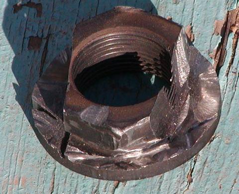
Hub nut after removal
Into the Good Stuff
I
removed the cam cover and put the harmonic balancer back on the hub. I didn’t put it on tight; just enough to hold
it in place, making sure the keying pin was in place. The goal was to clock the engine so that #1
cylinder was at TDC. I scrounged up a
couple long bolts and threaded these into the hub so I could use a pry bar
between the bolts to turn over the engine.
As much of a pain as the hub nut was, I kind of missed it, it sure was
handy for turning over the engine. Once
the OT mark on the balancer lined up with the raised mark in the center of the
timing chain cover I checked the cams for an indexing mark. Turns out there’s
more than one indexing mark on the camshafts.
I was 180 out so I turned the engine over again until the OT mark was
lined up and lo and behold, there were the indexing marks on both
camshafts. The marks are subtle but
unmistakable once you find them. They
are located just behind the front journal on each camshaft,
the marks are small square grooves, almost like a keyway groove, cut into the
camshaft that lines up perfectly with an identical size grove cut into each
journal.
Next
I removed the harmonic balancer and the hub, the hub just slides off. I removed all the remaining bolts holding
the timing chain cover and removed the cover.
It took a little careful prying but it came off. I removed the cover on the front of the cam
tower over the intake cam to get access to the intake cam sprocket (the exhaust
cam sprocket was exposed when all the distributor stuff was removed).
The
chain tensioner was next; I took it all off and everything, including the
piston, popped out. Then I removed the
upper chain guide between the cams by removing the two bolts holding it on.
The
next step was to remove the cam sprockets.
Each was held on by 6 M6 (10mm head) bolts. The bolts are locked in place by a big
folding washer that has a tab folded up on to the side of each bolt. I used a small chisel and a flat punch to
bend the tabs away from the bolts and then removed the bolts. I gently tapped the sprockets to get them off
the camshafts and by dropping down the intake sprocket first and then the
exhaust sprocket there was enough slack in the chain to allow me to lift and
remove the sprockets from the top.
The
chain was almost free; the plastic guide rail on the driver side was all that
was holding it in place. I removed the
two clip rings holding the guide on the studs.
Still not quite enough, so I unscrewed the studs and I was able to drop
everything out the bottom.
On
the front of the head there were two round shafts with a threaded hole in the
center of them. The one on the driver
side holds the idler sprocket, the one on the passenger side hold the upper
chain tensioner. I removed these by
putting a socket that’s bigger than the shaft over the shaft and threading a
bolt into threaded hole. As I tightened
the bolt against the socket it pulled the shaft out. There’s a small socket head bolt that comes
down from the head in front of the shaft on the passenger side that I had to
remove before doing this. There’s an
o-ring on each of these shafts and once it’s clear of the head the shafts come
out easy.
I
also wanted to replace the lower timing chain sprocket. The teeth seemed too pointy with almost no
flats on the tops. I had to buy a small
4” gear puller to do this. Found one for
$7 at a cheapo tool store. Figured if it
broke I could always go back and buy the fancy $35 model. The trick here is the puller has to be short
enough to fit on the sprocket without hitting the AC condenser. I greased the threads on the puller shaft and
the end of the puller where it contacts the end of the crank, got the fingers
behind the 2nd set of teeth on the sprocket and started cranking
away. I was sure the puller was going to
break because I was really cranking on it and nothing was happening. Suddenly there was a snap like something
broke, but no, the sprocket was coming off.
Kept cranking on the puller and the sprocket came right off.
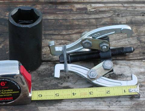
Small Gear Puller & 36 mm Socket
All
the timing chain components were now out except for the main tensioner
rail. The top of the rail sticks up into
the chain channel on the head. All that
holds it in the engine is a shaft that comes out of the block with clip ring on
the end. Removing the clip ring allowed
the rail to slide out but it runs into the edge of the head well before it
comes off the shaft. If only it was
about a ½” shorter there would be no problem.
This
was the point where I almost removed the head.
Someone on-line told me that the pin the rail was riding on was a stud, all I had to do was grab it with vice grips and
unscrew it. This may be true on the B36
or B38 versions of the engine but not the B35.
I tried it and soon discovered that on the B35 this is a press-fit pin
and my chances of removing it with vice grips with rail in place were nil. I went to the dealer and ordered a head
gasket, head bolts, new rail pin, etc. and resigned myself to pulling the head
to get the stupid rail off.
This was bugging me. Once the parts arrived I began removing the
exhaust manifold (very tedious job) and started thinking, “I’ve got a new rail,
I’ve got a new pin, why not cut off the end of the old rail with a hacksaw and
get it out of the way? Maybe that’s the
trick to this job.” Sure enough, it
worked. I cut off the top of the rail,
being careful not to damage the head gasket and it came right off. With the rail out of the way it was easy to
get a grip on the pin with the vice grips and using a pry bar between the vice
grip and the block I was able to wiggle the pin all the way out. I bolted the exhaust manifold back on and
got ready to put it all back together.
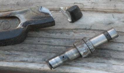
The cut rail and the pin
Assembly Preparation
Clean, clean, clean. Every part removed got cleaned. I removed all traces of the old pan and
timing cover gaskets with razor blades.
There were traces of gasket material all the way up the block to the
head gasket. Had to be
careful not to cut the head gasket since that’s what seals the top of the
timing cover. Followed
the scraping with more solvent cleaning.
All hardware, nuts, bolts, washers, cleaned until there was no grit or
grime to interfere with proper torquing.
I also removed the old oil seals from the timing cover and the
distributor housing and installed new ones.
I used a socket and hammer to remove the needle bearing from the idler
sprocket and used a vice to press the new needle bearing into the sprocket.
Assembly
I
started by installing the lower timing chain sprocket. I put the new sprocket in the toaster over
set at 400F and left it there for 30 minutes.
I made sure I wasn’t putting it on backwards (single row of oil pump
sprocket teeth to the rear) lined up the keyway with the key still on the crank
and quickly slid it all the way on the crankshaft. I checked it 5 min. later and it had cooled
enough to lock firmly onto the crankshaft.
I placed the oil pump chain on the sprocket.
Next
came the main tensioner rail. I put the 2 little o-rings inside the rail
(there are two grooves inside the rail for the o-rings) put the new pin in the
rail and installed the clip ring. It was
a little crooked when I held the rail & pin in place but close enough that
with a couple of light taps with a small hammer the pin began to go into the
block. As soon as that happened
everything straightened up and went right together. I had to hit the pin pretty hard to get it
all the way in so I held a hacksaw blade across the top of the pin and hit that
to keep from messing up the top of the pin.
Where the o-rings go
The
upper tensioner rail was next, made sure the lower end
of the rail was on top of the corresponding groove at the top of the main
rail. The o-ring was in good shape so I
reused it
I
installed the idler sprocket with the tall side of the sprocket to the
front. Again, the o-ring was in good
shape so I reused it. I put a little
assembly lube (moly grease) in the needle bearing just before assembly. On the front of the shaft there’s a little
curved cutout, make sure this lines up with the curved cutout on the front of
the head.
Next
the two studs that hold the plastic guide, the plastic guide, and the chain
went in. I made sure there was a flat
washer under each one of the studs (sets the height) and I applied Loctite Blue
to the threads. The guide is installed
behind the chain, with the opening to the front and the end with the angled
opening down. I had to install the chain
and guide at the same time since I couldn’t find a way to put on the chain with
the guide installed first. It’s a tight
fit and I had to twist the guide a little bit to get the studs in and
started. As soon as
that happens everything got easy.
I torqued the studs to 16 ft./lbs. I don’t know if the Loctite is necessary but
it looks like if those studs come loose the engine would self-destruct with
little or no warning.
Getting
the cam sprockets in was interesting.
First I put the timing cover and harmonic balancer back on to make sure
the crank was still aligned exactly on the OT mark. It was so I took the cover and balancer back
off. Next I checked the cam alignment
and found the intake cam had moved slightly.
I threaded a couple bolts into the end and used a pry bar to get the
indexing marks lined up exactly.
First
I made sure the idler sprocket was fully underneath the chain, it can easily
slip back on the shaft so that only one set of teeth are under the chain. I
could tell the 2 cam sprockets apart because the alignment pin on the exhaust
sprocket sticks out the front in order to clock the shaft that drives the
distributor rotor. Lifting the chain up
I put the exhaust sprocket in first and let it drop down near the idler
sprocket and then I slipped the intake sprocket inside the chain. I brought the intake sprocket up and rotated
it so the alignment pin was aligned with the hole in the cam flange and pressed
the sprocket in place. Once it’s aligned
right it slips right on (a couple light taps with a small hammer works
too). At this point the chain between
the intake cam sprocket and the lower cam sprocket on the crank is pulled
pretty tight. Feed all chain slack to
the passenger side of the lower chain sprocket.
I had to have someone hold the chain onto the lower sprocket while I put
on the exhaust cam sprocket because the chain wanted to slip one tooth while I
was doing this. I rolled the sprocket
into the chain so that the alignment pin lined up with the hole in the cam
flange and gently tapped on the sprocket until it slid in place. I put the folding washers in place and
screwed in a couple bolts on each sprocket to make sure they didn’t come off.
I
installed the new tensioner piston, old spring and new tensioner cylinder. I didn’t torque the tensioner cylinder, just
snugged it up. At this point I wanted to
check to make sure everything was aligned properly. I installed the timing cover (no bolts, just
used the alignment pins on the cover to hold it in place, the hub and the
harmonic balancer. Again I used a couple
long bolts threaded into the hub and a pry bar to carefully and slowly turn
over the engine 2 complete revolutions.
I stopped with the crank exactly on the OT mark and checked the indexing
marks on the camshafts. The indexing
marks were lined up exactly on both camshafts so I knew I had it assembled
right.
I
removed the balancer, hub and timing cover to re-inspect the chain
installation. Double checked the idler
sprocket to make sure it was under both rows of the chain, made sure the
tensioner rails were in right, all clips fully in place. Noticed I’d left the upper guide (between the
cam sprockets) off so I installed the new one and torqued the bolts to 16 ft./lbs. I torqued the
tensioner cylinder to 68 ft./lbs. and installed the
rest of the tensioner assembly.
I
recleaned the mating surfaces of the timing chain cover and coated the new
cover gaskets with a thin layer of hi-temp silicone gasket sealer. Thin is the key, I don’t like a lot of
squeeze out especially on the inside of the engine where it can come loose and
clog up the intake to the oil pump. The
gaskets are longer than the cover, I put them on the
cover and carefully trimmed the top edge flush with a razor blade. Next I used a toothpick to apply a small line
of Hondabond (A non-hardening gasket sealer used by motorcycle shops to seal
the crankcases of two-stroke engines.
Thanks to Jim Johnson @ Sandia BMW for this tip.) where
the head gasket first comes out of the block.
This is where the upper corners of the timing cover meet the block &
head. I used a small dead-blow hammer to
tap the cover in place on its locating pins and installed a couple screws on
both sides of the cover just to snug the cover down. Then I installed the 3 socket head cap screws
that attach the timing cover to the head.
The idea was to pull the cover up and in to get the best seal. Once I had everything snugged up I torqued
the 3 screws at the top to 7.5 ft./lbs. and worked my way down, torquing the M6
(10mm head) bolts to 7.5 ft./lbs. and the M8 (13mm head) bolts to 16 ft./lbs.
Now
it was time to put the oil pump & pan back on. First I trimmed the timing cover gaskets
flush with bottom of the block. Then I
coated the pan gasket with a thin layer of silicone to hold it in place and
with the oil pump in the pan slid everything up into place. Assembly was the reverse of
installation. I put the pump sprocket in
the chain and fit the spline shaft of the pump into the sprocket. I torqued the 3 M8 bolts to 17 ft./lbs. and the 2 M6 bolts to 8 ft./lbs. I torqued the nut that holds the sprocket to
the shaft to 35 ft./lbs. I put a line of Hondabond across the point
where the timing cover gasket meets the pan and I torqued all the M6 bolts that
hold the pan on to 8 ft./lbs. When I installed the cast cover to the bell
housing I torqued the torx bolts to 34 ft./lbs.
I
went back up to the cam tower to finish installing the cam sprockets. I installed and torqued the M6 bolts to 8 ft./lbs. and bent the folding washers up around each bolt on
both sprockets. I installed the cover over
the intake sprocket (8 ft./lbs.).
The Hub Nut, Part 2
The
last big thing to do was install the new hub nut. Install the hub, put on the flat washer and
then the hub nut. I didn’t have a torque
wrench that would go up to 325 ft./lbs. so I
improvised. I used an in-line scale for
measuring loads on cranes. Any type of
pull scale that would accurately read to 81 lbs. would do. I then put my cheater pipe on my breaker bar
and measured exactly four feet from the head of the breaker bar to a spot on
the cheater pipe. I marked this spot
with a circle of tape. The idea was that
81 lbs. applied on a 4 foot lever will produce 324 ft./lbs.
of torque and that should be good enough.
It
took 4 people to do it but it worked.
With the hook of the scale at the 4-foot mark on the pipe I pulled real
hard. One person was on the brakes, one
person watched the scale, one person with their hands near but not on the
cheater bar (if something gave way I didn’t want the bar to put a big dent in
my fender) and me pulling on a bar through the hook on the bottom of the
scale. It took a couple tries and the
socket had to be repositioned but the scale finally reached 81 lbs. The breaker bar flexed several inches but
didn’t break.
Finishing Up
I
put new gaskets under the cam cover and tightened all the nuts to 8 ft./lbs. I lowered the
engine back onto the engine mounts and torqued the nuts to 35 ft./lbs. From here on
out it was a matter of replacing all the stuff I had pulled off to make room
around the front of the engine. For
torquing I tightened all M6 hardware to 8 ft./lbs.,
all M8 hardware to 17 ft./lbs. I
replaced all the coolant hoses and put in new oil & filter. I’m sure there’s a torque spec. for the fan
nut but all I did was have someone squeeze the fan belt while I smacked the
wrench with a hammer to tighten the fan.
The last thing I did was add antifreeze (1
gal.) and distilled water (about 1.5 gal.).
Start Up
Scary.
Very scary, for me anyway. When the engine started I could hear the
chain. The spring in the tensioner isn’t
really adequate to tension the chain, oil pressure does this. I was too much of a wuss to rev the engine to
build some oil pressure so I just let it idle.
After 10 minutes the chain noise was almost gone. After about 5 more minutes with quite a bit
of that time at 2-3K RPM the chain noise was gone and all was right with the
world. I have heard there is a way to
prefill the tensioner with oil but I don’t know how to do that. That would probably make the noise go away
much faster.
300 Miles Later
No
problems, no leaks, no funny noises. Been up to 6500 rpm with no problem.
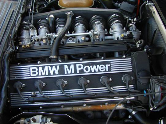
All done, drivers' side
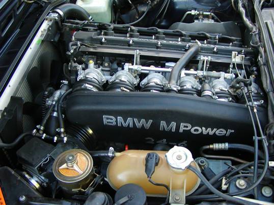
Passengers' side
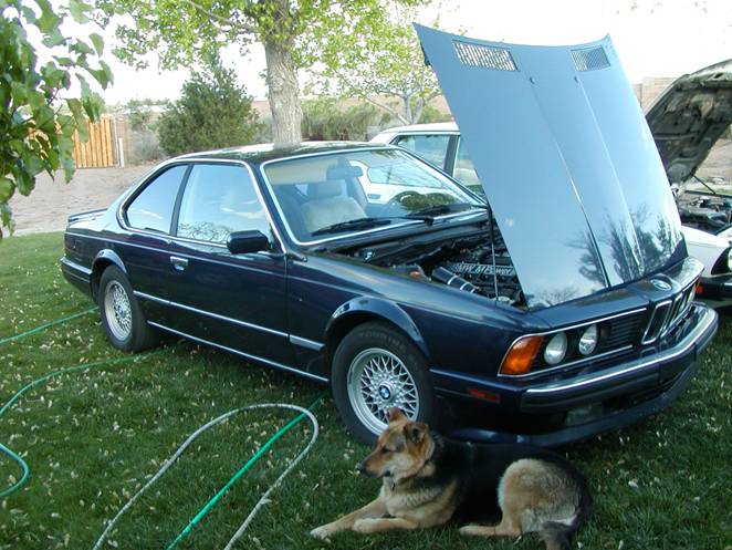
The car