One of the strong features of the WXN software suite is the ability to support sensors and add-ons not supported by the weather station. Because of the 1-Wire techonology employed adding soil temperature sensors is not a major undertaking.
Soil temperature is measured usually at a 6" and/or 8" depth. The server supports two soil temperature sensors. While the sensor could simply be sealed and burried, it is much more convenient to mount the sensor on a strip of etched PC board of appropriate length and then bury that.
Circuit
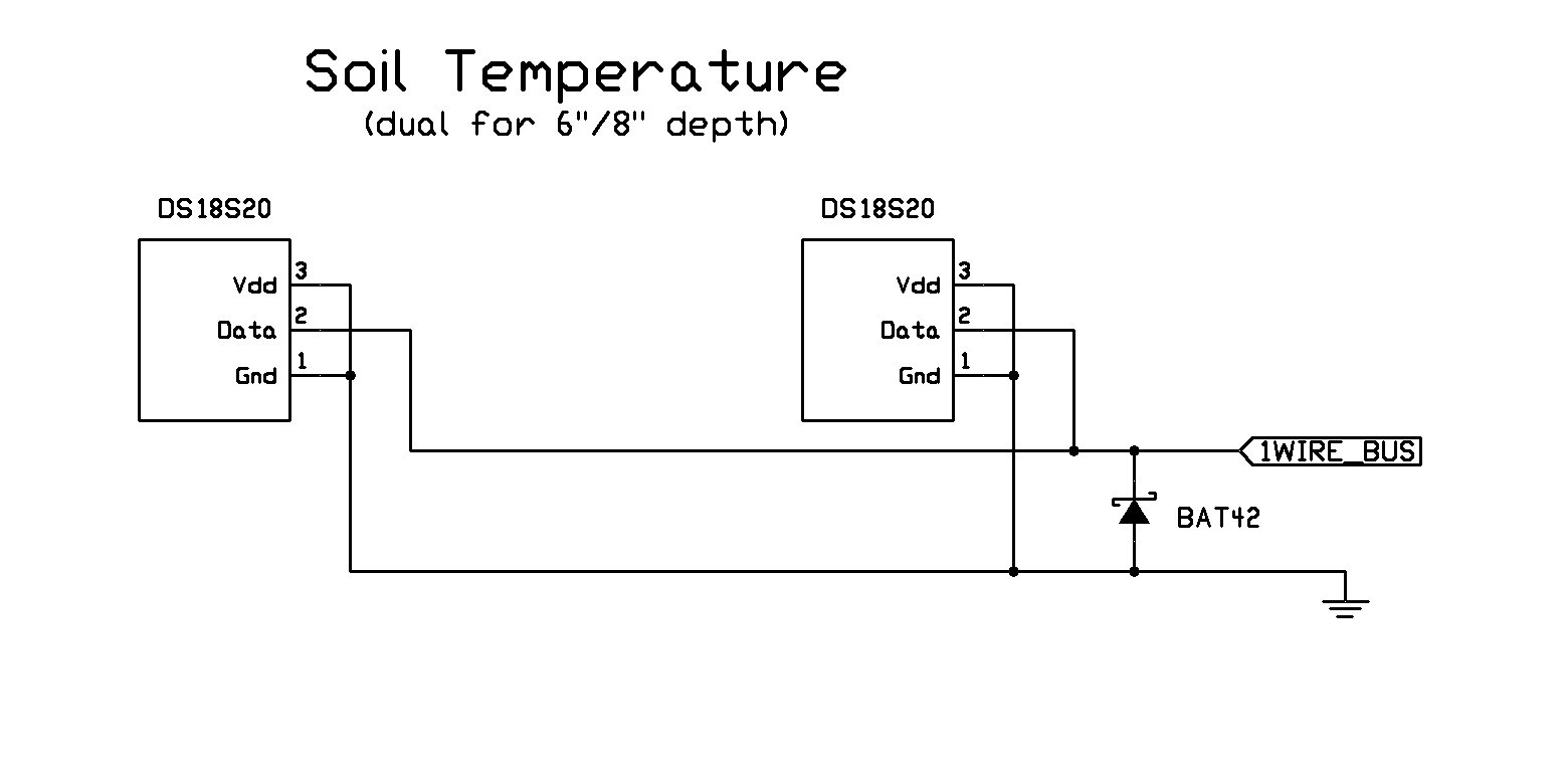
In all cases, the two outside leads are grounded and the center lead is connected to the 1-Wire bus. If the temp sensor is not at the end of the line, you will need to come up with some means of daisy-chaining more devices on the same line or connecting them in parallel. The general connection scheme is shown below. If the image is not real clear, right-click and select 'View Image'.
Construction
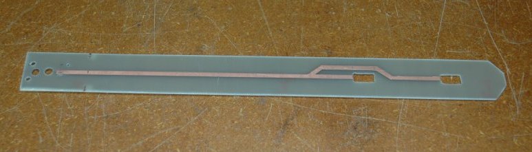
Board - The layout of the PC board is shown below. Note the rectangular openings for the temperature sensors.
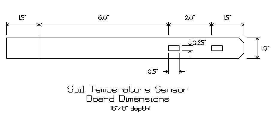
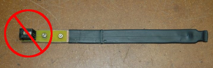
The only dimensions that are important are the ones that determine the depth of the sensor from the surface. If you design your own, be sure you allow a portion of the board to extend above the surface of the ground. This is important for drainage and to help keep the connections to the board dry - even though it may be sealed. One note - do not do what I did the first time around - put a RJ11 socket on a PC board to connect up to the 1-Wire bus. Big mistake. In one case, the wires in the RJ11 socket had completely erroded away.
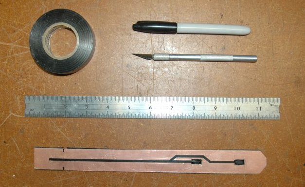
The etch mask for the PC board is easily made from electrical tape and/or permanent marker. The picture below shows the materials used to mask the board. To start, the front and the back of the board is completely covered with a single layer of electrical tape. The pattern on the front of the board was made by using a hobby knife/straight-edge and then carefully peeling away the tape. The board shown below is ready to etch.
Note that the rectangular openings for the temperature sensors were cut before applying the tape. I used a Dremmel tool to make the openings - first by drilling a series of small holes around the perimeter of the opening and then a small grinding tool to smooth things out.
Etching is accomplished using a PCB etchant solution available at Radio Shack and most other electronic supply houses. The etched board, front and back are shown below.
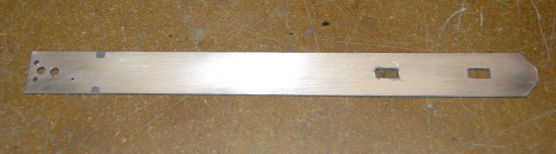
Note the strain relief holes drilled on the LH end of the board.
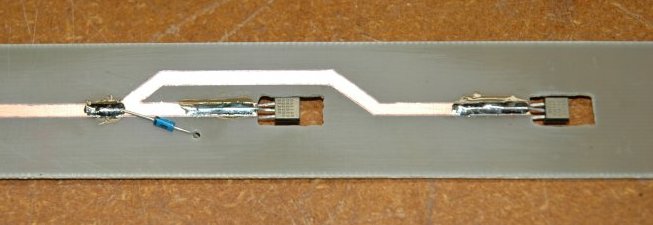
Wire - In these steps, the sensors are installed and cable attached. Details that must be followed:
- The center lead of each DS18S20 is soldered to the front of the board while the two outside legs are soldered to the back side.
- The cathode lead of the protection diode has been sweat-soldered to the top trace. A small hole was then drilled and the anode pushed through and soldered to the backplane of the board.
- The center two conductors in a RJ11 ribbon cable carry the 1-Wire bus and ground. At this point, it will not matter which one is connected to what. One lead is sweat-soldered to the etched strip on the top of the board. Drill a small hole in the board as shown below and solder the second lead to the backplane.
- Some sort of strain-relief must be allowed for. I drilled two holes and looped the ribbon cable through them. Be careful when dressing the cable. One of the two outside leads carries +5V. If this lead were to short to ground or the 1-Wire bus, damage would likely occur.

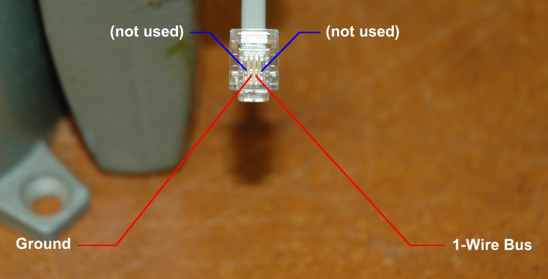
With your cable cut to the the desired length, attach the RJ11 connector to the end of the ribbon cable as shown below. You will need to verify which lead went to ground and which went to the 1-Wire bus trace. You might want to verify this with an ohmmeter before and after you attach the connector.
Test - Important! Before sealing the unit, test your wired assembly with the 1-Wire utilities ('tstfind' and 'temp') to insure they are working correctly. This will be your last chance to fix anything easily!
Seal -The last step in the assembly is to seal the unit with heat shrink tubing lined with glue. Be sure you use the type that has the hot-glue integrated into the tubing. This is important for to get a good weather seal. When shrinking the lower tip, I have found it helpful to clamp the end after heating it and it shrinks. This will insure complete closure and seal of the lower end. I also use coax seal to seal around the cable at the top and then apply shrink around that. Since sealing the sensor and connections in this manner, I no longer have had corrosion problems or sensor mal-functions.
Once the sealing operation is complete, take a permanent marker of some type and mark where the ground level will be. This will 6" above the first (or only) sensor. This will be used as a reference when doing the installation later.
Installation
Tools - To make installation a lot easier, I would suggest going to your local hardware outlet and getting a piece of steel stock 1" x 3/16" and cutting it to an 18" length. I tried using large screwdrivers and other means, and nothing really worked well until I tried this.
Using the hammer, drive the steel pilot shaft down into the ground about 10"-12". You want more depth than you will need.

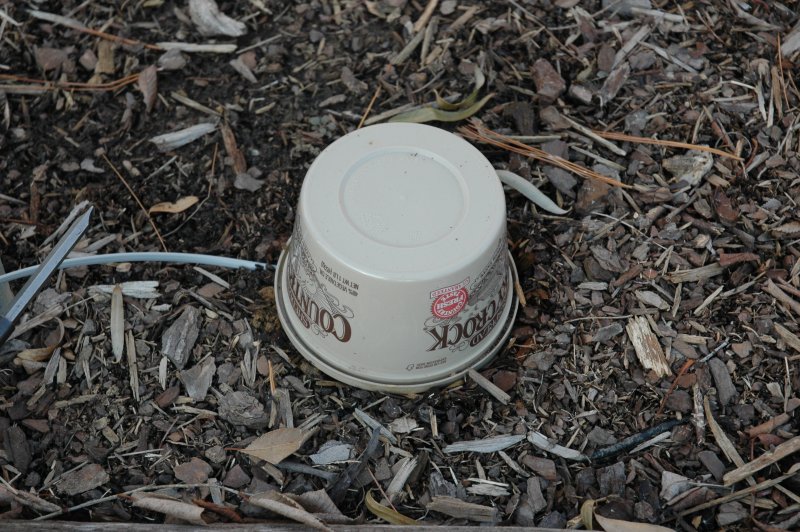
Although not required, I recommend using additional protection for the part of the sensor above ground level. Used "Crock" containters work well. Cut two slits in the lid. One in the center and the other to the side.
Remove the pilot and gently push the sensor into the slot left by the pilot. If you encounter any resistance, withdraw the sensor and pilot the slot again. With the Crock lid resting on the ground the mark you placed on the sensor during construction should be just at the point where it is passes through the lid. Put the "lid" (actually the Crock tub) on the assembly to finish this phase.
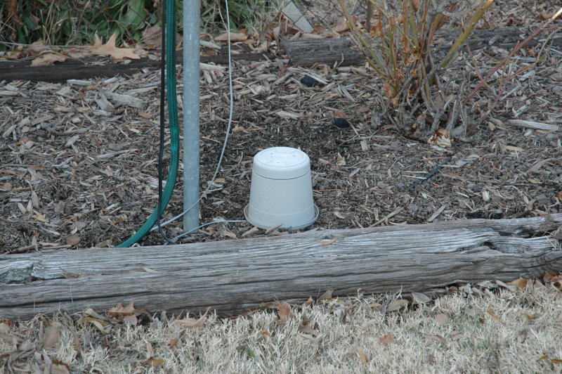
One last note! - I soon found out that the Crock was not very UV resistant. In a matter of a month or two it cracked and I had moisture problems. The final solution was to add another container on top of the Crock. Medium sized outdoor flower pots work well as shown below.
One other solution that I have used in areas where there was a possibility of damage from someone kicking or other possible damage was to use patio liner blocks in a square with a square block to cover the entire assembly. I drilled holes in the liner blocks and used 12" pieces of rebar driven into the ground as anchors. This works very well. When I get a picture of an existing installation, I will put it up here.
Configuration
Configuration is covered in the documentation for the server. It can be viewed at N4XI's web site.