Rear Turn Signal Mod from Electrical Connection to make them Running & Brake Lights:
This is a mod I considered for the Shadow but never did. I came across a web site (scroll to the bottom of the page) which showed the Electrical Connection kit installed on a Drifter and liked the idea again. I got the kit and installed it. It's a definite improvement, especially at night. It never hurts to have extra lights in the back as well as the front. I did not follow instructions, however, with the installation since the connectors supplied with the kit make a bulky package and there is not a lot of room behind the brake light. I soldered all the connections and found that you can do all the work off the bike with only a couple of easy connections to make once you install the brake light and turn signal bar back on the bike. Below is how I did it. Gadget also has a description for this installation but it looks like the newer kits are improved somewhat and, more importantly, the configuration of the turn signals has changed, making installation a lot easier than shown on the two web sites above.
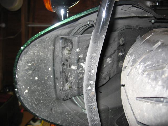
Take off the plastic cover and disconnect the turn signal and brake light connectors under the fender. It helps to have the bike on a lift and taking off the cross bar will make it really easy. I didn't take off the cross bar but found if you lie on your back it's easy to work in the confined space.
Remove the brake light and turn signal bar. It's obvious which bolts to remove under the fender. Note the grommets on each wiring harness. Don't loose those.
Turn signal lenses removed. On the 2006 Nomad, one screw needs to be removed on the under side of the turn signal housing. One important tip is when reinstalling the lenses, insert the longer, bottom tab with the screw clip first and then push in the upper part to engage the little lip into the notch in the housing. If you try it the other way (upper part first) you'll screw up the sealing gasket in the housing pushing in the longer, lower tab. Trust me on that one!!
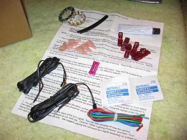
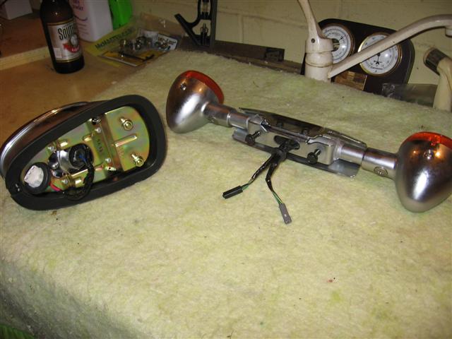
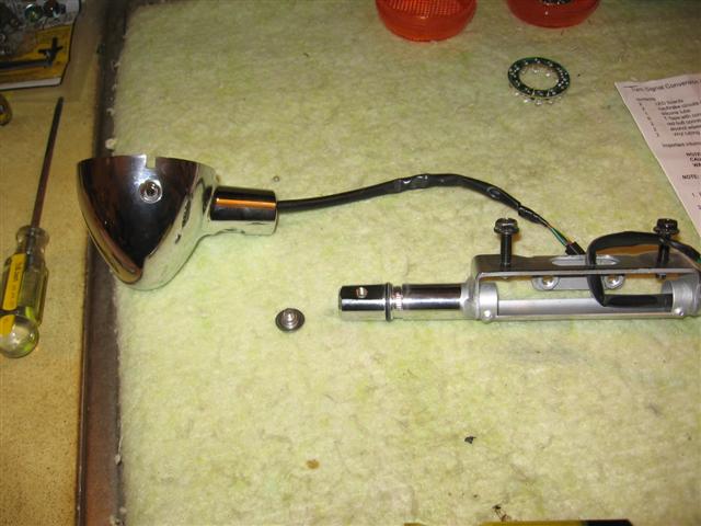
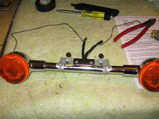
These are the parts in the kit. Note the two connector pins on the LED boards and the two harnesses. I didn't use any of the connectors, though they are quite neat and may come in useful on another future project requiring a quick connection where there is more room to work with.
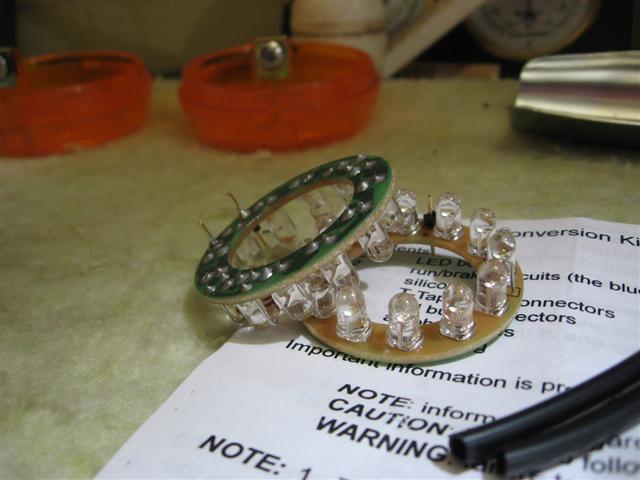
Use the alcohol swabs to clean the LED's and inside of the lenses, put a dab of silicone on each LED and glue the LED boards to the inside of each lens, centering the board inside the lens. Note that you should orient the connector pins at 180 degrees from the lens screw. It takes a couple of hours until they are secure enough to reinstall on the turn signal but I would then leave them for a day or so before riding.
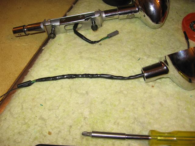
I started with the turn signals. I took off each signal from the bar. You'll have to rock the signal a bit to get it off the bar and off the O-ring. Pull out the wiring from the bar and remove the electrical tape. I cut the protective sleeve in half to expose the wires. I had figured out by this time, that rather than using the connectors, soldering the black LED wire to the green wire will make a neater connection.
Feeding the LED wires thru the bar turned out easier than I thought.
I tried feeding the LED wires thru the grommet but the turn signal wires are molded into the grommet.

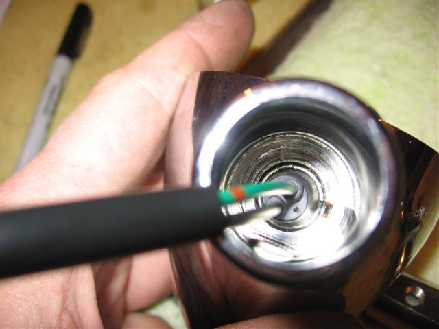
I pulled out the grommet and discovered a slot thru which I could feed the LED wires. Maybe they read Gadget's web page!! On the other signal, I just pushed the grommet over a little with my fingernail and then could feed the wires thru with having to remove the grommet. Feed about 12-15" of LED wire thru. The kit provides way more than you'll need.
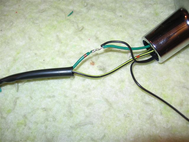
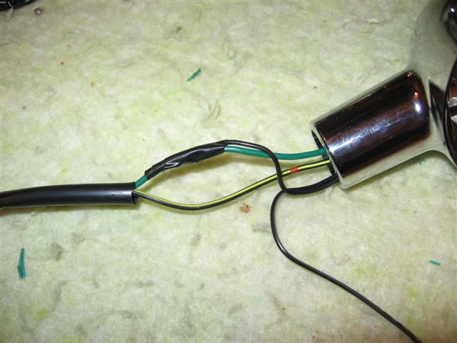
Solder the black LED wire to the green wire. Trim the black wire to suite but make sure you split the LED wires first and leave the black-white one about 12-15" long, feeding it thru the 3" or of the protective sleeve you have left. Tape the soldered connection, push the protective sleeve gently back into the turn signal housing and tape up the wires up to the connector.
Do the same for the other signal and set aside for now. Remember to put the grommet back over the wiring.
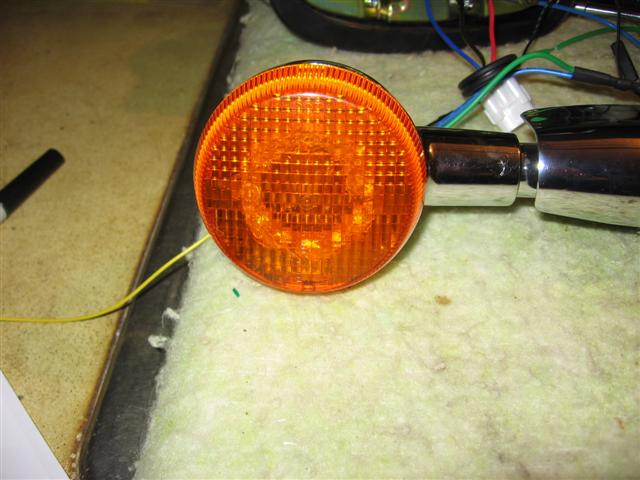
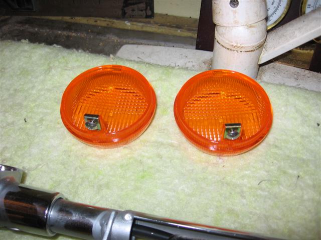
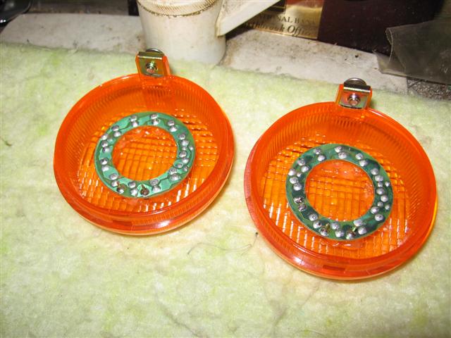
This shows the lens with the LED's. In daylight it will be visible but it's not too tacky.
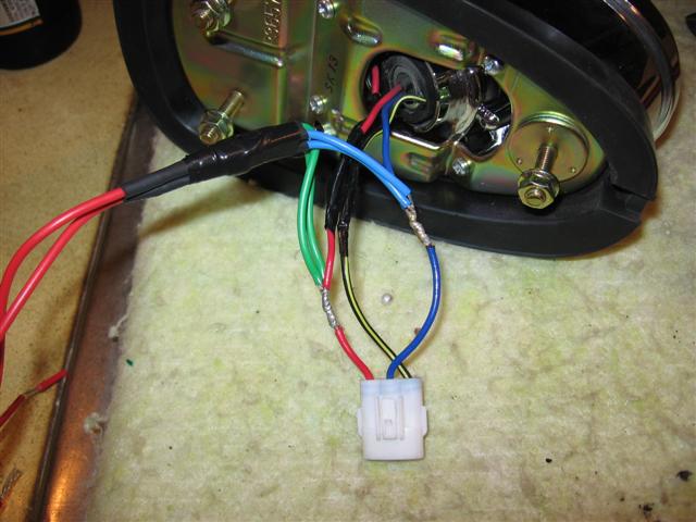
I used the same method to attach the wiring to the brake light. Again, there is not much room once you install the brake light on the fender and this makes for a much more compact installation. Trim the kit wiring harnesses as short as you can get away with.
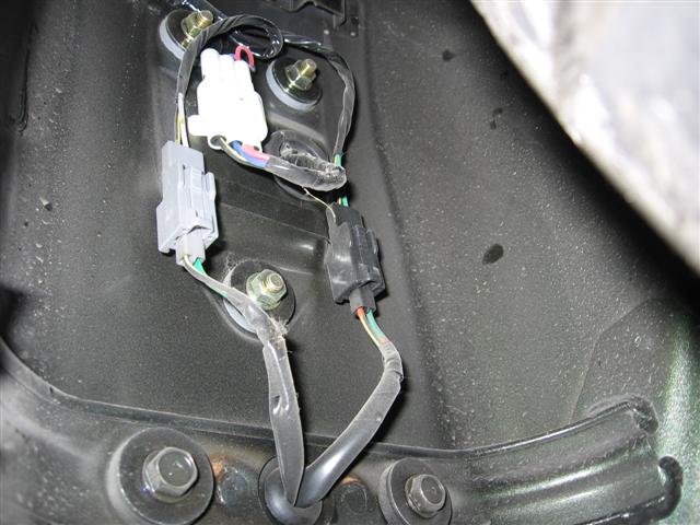
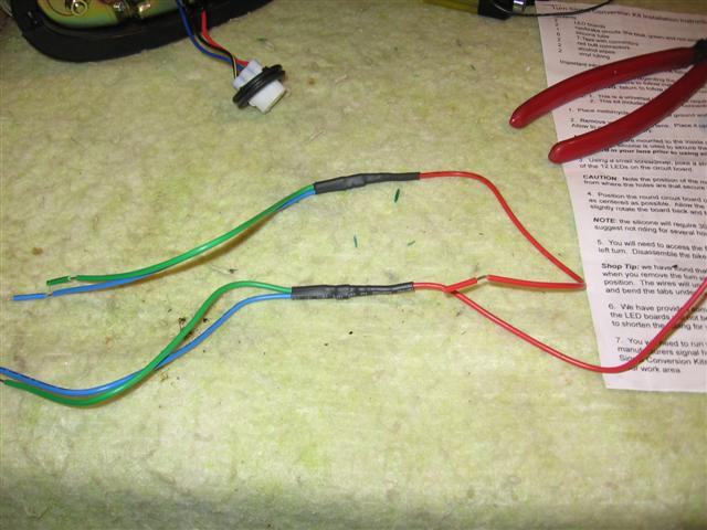
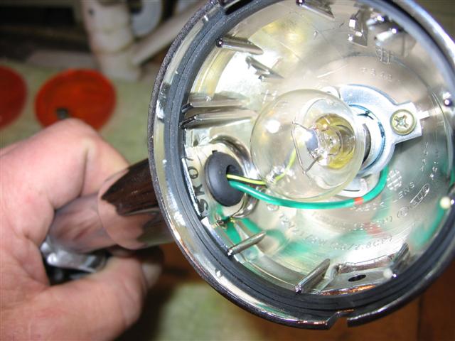
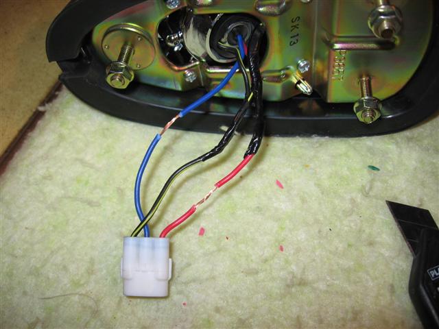
Connect as shown. The red wire is the running/license plate + wire, the blue is the brake light + wire. The black/yellow is the common ground.
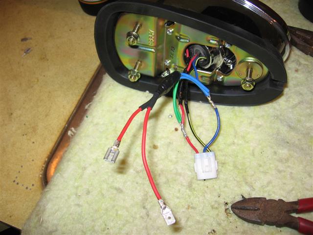
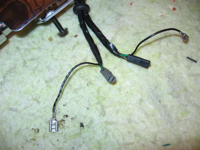
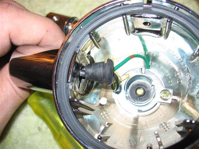
The small black/white wires from the LED's connect to the two red wires. It does not matter which you connect to which. I used spade connectors to make the connection under the fender easier. Tape up the wiring on the brake light but not too tight. Remember the grommet. Once you have the two assemblies above, install them back on the bike and you'll only have to connect the red and black/white wires inside the fender.
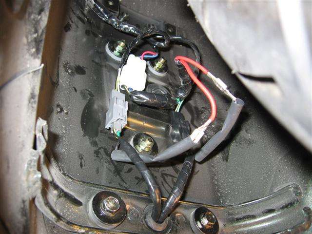
This is everything installed on the bike. I used a length of heat shrink take to protect the connections for the LED wires.

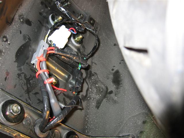
Some wire ties keep things neat. Put the cover back on and you should be good to go.
Everything worked as it's supposed to and the LED's are really bright though the color is more of a rose color than a dark red but they sure light up the back end.