How many of us understand the detailed workings of the lock on our black powder long gun or pistol? Not as many as should do so, even among experienced shooters, I suspect. Since such an understanding is central to the consistent and efficient functioning of our guns, and also has significant safety considerations, a discussion of basic lock construction and function seems appropriate.
There are many different types of locks...flint, percussion, front and back action, side action...but the essential action of all is the same, any differences mostly involving refinements, not the basics. Thus, when we discuss a typical lock, the principles can be freely applied to most types, flint or percussion
NOTE: This is not a quickie FAQ. Several fairly large scans have been prepared to illustrate the nomenclature for the various parts. I suggest you look at the Flint Lock Terminology FAQ and the Percussion Lock Terminology FAQ to familiarize yourself with the terms we will be using. It would also be of great help to your understanding if you read this FAQ with a lock in hand and cycled it, maybe even disassembled it, as you read.
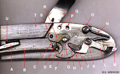
We will use this scan of the internal view of the percussion lock as we make our way though the discussion.
The heart of the action of the lock is the tumbler (F). It is at the center of the chain of events, and all are related to it. On the lockplate side, it has a heavy projection in the center, round, like half an axle. This projects through the lockplate, and the hammer (Q) is fitted rigidly onto it, so that the two move together. As the hammer moves back and forth, the tumbler rotates, also. On better quality locks, there is also a smaller projection on the other side of the tumbler, the other end of the axle (G). A bracing piece, the bridle (See Percussion Lock Terminology FAQ) fits down onto the lock plate, straddling the tumbler and sear, and is rigidly screwed to the lock plate. The smaller axle of the tumbler fits into a hole in the bridle, and this makes a much more sturdy, firm mechanism, since the tumbler axle is now supported on both ends.
All the power for firing the lock comes from the main or hammer spring (A,B). It is fastened to the lock plate in front of the tumbler (so what we are discussing here is a 'front action' lock). It is in the form of a "V" lying on its side, open end toward the tumbler. The upper limb of the V is stationary, the lower limb does all the moving. Compression of the spring by closing the gap in the V, or moving the lower limb upward, stores energy.
The tip, or nose, of the lower limb of the mainspring makes contact with the circumference of the tumbler in one of two ways. The graphic above shows the contact being made through a link called the stirrup (C). The stirrup rides, at its upper end, on the projecting stirrup arm of the tumbler (R), and attaches to the nose of the mainspring through a two-fingered claw (D) on the nose of the lower limb of the mainspring. In the more common way of attachment, shown in the Flint Lock Terminology FAQ, the nose of the mainspring is simply formed into a strong hook, and the tip of the hook makes contact with the tumbler on a curved projection called the cup of the tumbler. This hook and cup arrangement is found on most all military locks, and on most civilian ones, as well.
Whichever method of contact is used, downward pressure from the mainspring causes the tumbler to rotate around its axle in a counterclockwise direction, which moves the hammer toward the nipple or frizzen, firing the gun. Of course, cocking the gun by pulling the hammer back rotates the tumbler clockwise and forces the lower limb of the mainspring upward, storing energy in preparation for firing.
Now, all we need is some way to cock the gun and have it stay cocked and ready to fire, but not to do so until we are ready.
Simple. A plain old ratchet arrangement takes care of that. A ratchet mechanism is composed of two parts, the ratchet and the pawl. In this case, the ratchet is the full-cock notch cut into the circumference of the tumbler on the side opposite the mainspring, and the pawl is the nose of the sear (J).
The sear is composed of three main parts, the body (L), the nose or pawl (J) and the bar or tail (M). It is fastened to the lockplate behind the tumbler with a screw (O) around which it freely rotates. Above the sear, the sear spring (N) is fastened to the lockplate, and positioned so that it is constantly trying to rotate the sear in a clockwise direction around its pivot screw, thus forcing the sear pawl to rub against the circumference of the tumbler. By cutting a notch in just the right spot on the circumference of the tumbler, so that the pawl of the sear will fall into it under pressure from the sear spring, we have a mechanism which allows the hammer/tumbler to rotate freely in a clockwise direction, but prevents it from rotating in the other.
Now, we can pull back on the hammer, which will rotate the tumbler clockwise, compressing the mainspring. When it has rotated enough, the sear nose falls into the full-cock notch, and the tumbler is prevented from rotating counterclockwise. The gun is cocked. All we have to do to fire it is to knock the sear nose out of the full-cock notch, and the tumbler rotates counterclockwise rapidly under pressure from the mainspring, causing the hammer to fall. Boom.
Because a cocked gun is a dangerous gun, we add a refinement, the half-cock notch (I). It is positioned on the tumbler edge in a proper position to work about half-way between hammer down and full-cock. Because it's not concerned with firing the gun, but only with safety, its form is different than the full-cock notch. Whereas the full-cock notch is just that, a notch, the half-cock notch is actually a slot . When the sear nose falls into it, it cannot get out by simply moving upward, so pulling the trigger to rotate the sear won't work, won't fire the gun. The hammer/tumbler must be rotated a slight amount toward full-cock, the trigger depressed to clear the sear nose from the slot, and the hammer can then be let down.
As noted before, the sear spring keeps the pawl or nose of the sear in constant contact with the circumference of the tumbler. This can cause a problem, now that we have that extra notch, the half-cock notch. When the sear nose is forced from the full-cock notch, the tumbler begins its very rapid rotation, and at the same time, the sear spring forces the sear nose back into contact with the tumbler. When the half-cock notch rotates under the sear pawl, there's nothing to prevent the pawl from falling into it. If it does so, something usually breaks, either the tip of the sear pawl or the lip of the half-cock notch.
There are two ways to prevent this from happening. The most straightforward is to use a simple, non-set trigger on the gun. Such a trigger, when pulled, forces the sear bar upward, disengaging the sear pawl from the full cock notch and allowing the gun to fire. Because the normal method of using such a trigger results in the sear bar being pushed upward and *held in that position*, the sear nose is preventing from falling into the half-cock notch, and the tumbler can safely rotate fully counterclockwise. Problem solved.
The second method involves the use of a fly in the tumbler (H), and is the method which must be used if a set trigger is used. A set trigger functions quite differently than a simple trigger. A set trigger is a self-contained mechanism on its own, designed so that when the trigger is fired, a bar snaps upward, striking the sear bar of the lock and knocking the sear nose from the full-cock notch. Once this has happened, though, the trigger bar instantly falls away, releasing all pressure on the sear bar, allowing the sear spring to force the nose of the sear back into contact with the tumbler. Unless something is done to prevent it, the sear pawl will fall into the half-cock notch. The fly is there just to prevent that from happening. The fly is a little piece-of-pie shaped metal part that pivots in a hole drilled on the tumbler, at the tip of a similarly shaped slot in the tumbler, right above the half - and full-cock notches. It is free to rotate a few degrees, and is positioned and shaped to prevent the problem we are concerned with. When the pawl of the sear is forced from the full-cock notch and the tumbler starts its sudden and rapid rotation, inertia makes the fly hold still, and this results in its rotating into a position to prevent the sear pawl from engaging the half-cock notch. The lower edge of the fly is shaped so that it forces the pawl to ride over the half-cock notch before making full contact with the tumbler, again. Once more, problem solved.
On to other things. What's the difference between front-action and back-action locks? Very little. The essential difference is that the mainspring is on the muzzle side of the tumbler in the front-action lock and on the butt side of the tumbler in a back-action lock. This, of course, means that all other parts are reversed. If you think about it a moment, you'll see that, because the tumbler and hammer must still rotate in the same direction, the direction of some forces must also be reversed...the mainspring must exert its force upward, not down, for instance.
The part of the tumbler axle which protrudes through the lockplate is round for a distance equal to the thickness of the lock plate, then is square. The hole for this part in the cock is also square. The end of the axle is bored and threaded for the tumbler screw. The angle at which the tumbler and cock are fastened together is critical, in order for the geometry of the tumbler notches, mainspring attachment to the tumbler and the relationship between frizzen/nipple and flint/hammer nose to fit together correctly.
You may have noticed that there is a sear spring screw, and a frizzen spring screw, but that there is no mainspring screw. That's because the mainspring is held in position only by tension on the spring. There is a stud on one limb which fits into a hole in the lockplate, and the tip of the upper limb is shaped into a thin wedge (U) which fits into a thin slot in the bolster (T). With these two in place, when tension is put onto the lower limb, the mainspring is held firmly in proper position. All that's required to remove it is that the spring be compressed , and it can be lifted off.
No discussion such as this can show you all the relationships and functions in that fascinating machine we call the lock. The best, maybe the only, way to learn them is to take some locks apart, study the parts and how they interact. Most educational, and fun, too.
For an explanation of how the trigger works to set this whole train of events in motion, see the Trigger Function and Terminology FAQ.
Copyright ©1997 B. E. Spencer